
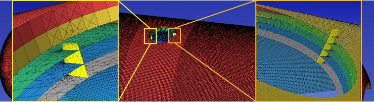
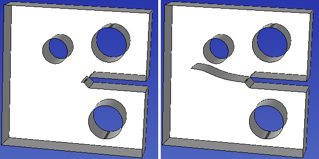
Crack insertion through a layered material structure in a tank design. Center: Crack preview locations. Sides: Inserted cracks.
Crack Insertion and Propagation
Overview
SimModeler provides easy access to the crack insertion and meshing functions developed in MeshSim Crack. Different CAD formats as well as discrete models (finite element meshes with no underlying geometry) can be loaded into SimModeler to perform a crack propagation simulation for a damage tolerant design study. SimModeler provides to the user a graphical interface to perform all required steps to set up a crack propagation simulation: define the analysis attributes (loads, boundary conditions, etc.) for the simulation, define the crack and preview it before insertion, mesh the model, and prepare it for preprocessing. SimModeler will then run a user defined number of crack propagation steps: running the solvers, post processing the analysis results at each step to determine the new increment of crack growth, updating the model and mesh to reflect the growth. The results of the simulations are then displayed in an easy-to-use GUI to query information about the simulated crack growth.
Capabilities:
- Types of crack surfaces that can be used to initiate crack propagation process: elliptical, rectangular or a combination of the two. One or more cracks are allowed in the implementation
- Automatic meshing of the crack surface. Singular wedges or non-singular elements are supported
- Continuous linkage between geometric entities and meshes produced for each step in the crack propagation simulation provides a robust process to automatically assign boundary conditions and loads onto each generated model
- Automatic batch processing and post-processing using commercial FEA packages
Out-of-plane Crack Propagation: Validation Case
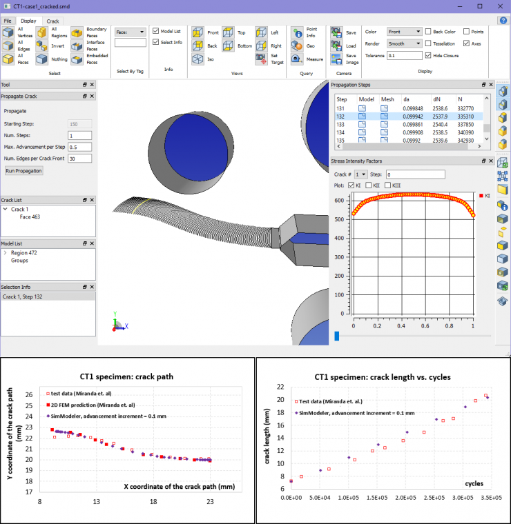
In the above example, literature data (Miranda et. al, "Fatigue life and crack path predictions in generic 2D structural components", EFM 70, 2009) was used to validate the implementation in SimModeler.

Crack Insertion Preview
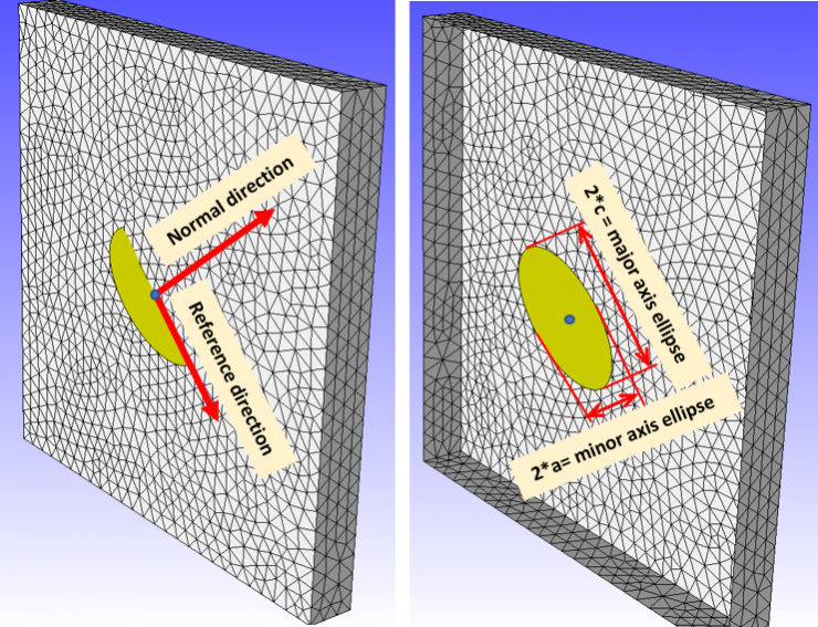
A crack surface preview provides useful feedback to assist the user in defining the desired crack surface.
Typical Mesh for an FE Model Containing a Crack
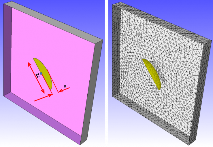
The surface used to define the crack is trimmed to the model boundary, creating a non-manifold face within the model. The new crack geometry is then meshed. The picture above shows a typical mesh for an elliptical crack surface. Front surface is hidden to display crack surface.
Crack Propagation Display
The updated crack surface is available for display purposes along with the entire set of crack advancement increments.