
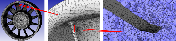
Crack propagation simulation - Entire FE mesh (Left), Close-up view at crack location (Center), Crack surface and surrounding mesh (Right)
Crack Propagation Life Assessment
The Challenge
Crack propagation life assessment of engineering structures is an integral part of well-established Damage Tolerant Design (DTD) practices in the aeronautical industry. In recent years other industries have adopted DTD procedures or introduced standards to design components that pose safety concerns. Structural Health Monitoring and Probabilistic Rotor Design which make use of fatigue and fracture methods, emerged in an effort to better quantify inspection intervals, set maintenance procedures or assess the risk of failure. The Digital Twin concept laid out by AFRL and NASA, re-emphasizes development of three-dimensional deterministic damage accumulation models reinforced by probabilistic methods to assess structural integrity of an aircraft structure. There is a clear need for robust and easy-to-use damage modeling capabilities at the component level to give more accurate predictive life assessment capability in various industries.
The Solution: Crack Insertion/Propagation Tools from Simmetrix
Several finite element modeling capabilities have been developed at Simmetrix to satisfy the industry level requirements for crack propagation simulation and life assessment. The procedures employ existing component level CAD models or finite element meshes to efficiently reuse data developed in the design process. The crack insertion process allows a planar or non-planar surface definition to represent the initial crack surface which can then grow into an arbitrary shape during propagation. Multiple cracks may be inserted and propagated during a single simulation. Maintaining the geometry-mesh relationship during the crack propagation simulation allows the boundary conditions and loading for each propagation step to be consistently applied. Both crack insertion and propagation are done using robust and fast local remeshing procedures which only affect the mesh near the crack, allowing easy recycling of an existing stress analysis. These procedures can be used with any structural analysis code (they do not require any special element formulations or any capabilities specifically related to crack modeling) and support all of the analysis code's capabilities. Validation cases have been done to verify stress intensity calculations and validate the life assessment procedure.
Component Level Example: Generic Turbine Blade Under Centrifugal Loading
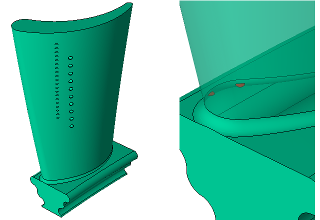
Overall view of the generic blade model and a close-up at the root of the leading edge of the airfoil where two cracks are seeded at different elevations along the radial direction of the blade.
Animation of the simultaneous growth of two interacting cracks. Crack propagation is not constrained to planar mode (both crack surfaces turn into each other when they partially overlap) and the interaction between the cracks is captured in the FE models associated with each advancement increment. The entire crack propagation simulation is performed automatically.
Mixed-Mode Validation Example
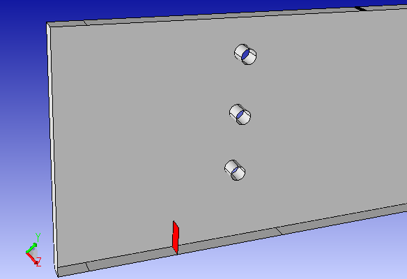
3D model setup for validating crack propagation path prediction against measurement data published in: A. Ingraffea and M. Grigoriu, “Probabilistic Fracture Mechanics – A Validation of Predictive Capability”, Report 90-8 AFSOR.
Animation of 3D crack propagation progression completed with SimModeler. Click on the image link to see the full 200-step propagation.
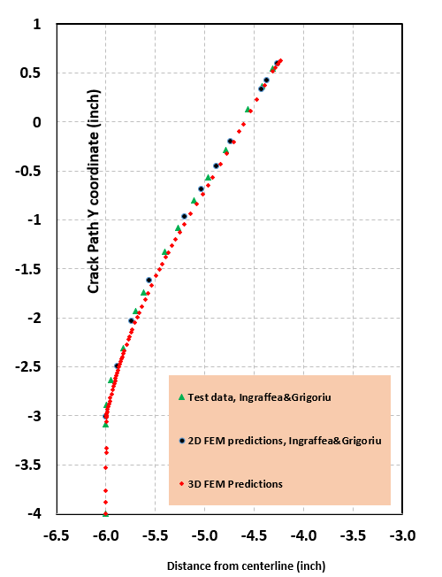
Crack path profile as measured and predicted using 2D modeling by A. Ingraffea and M. Grigoriu and, 3D prediction using SimModeler